
for older models this is done by prying out the sealing cap and unscrewing the nuts

for newer models it is just a matter of pressing on the studs one at a time while lifting the acoustic cover slightly
BMW call these cylinder head gaskets (which they are) while others may call them the camshaft or valve covers because they cover all these items.
The VANOS kit (which include inner gaskets) parts numbers are 1112 9 071 589 / 1112 9 071 590 while the NON-VANOS part numbers are 1112 9 069871 / 1112 9 069872.
You will also need some anti-friction rubber coating (glycerine does fine), Drei Bond (Silastic, Permatex or equivalent) sealer. It is also a good idea to buy new rubber grommets (you'll need 22 of them) for the cover.
Remove the acoustic cover:
for older models this is done by prying out the sealing cap and unscrewing the nuts |
for newer models it is just a matter of pressing on the studs one at a time while lifting the acoustic cover slightly |
Remove air inlet and battery terminal:
 remove suction-filter housing with air-mass sensor |
 unfasten battery positive terminal on battery support point |
Remove ignition coil cover and coils:
 remove cover from ignition coils from both sides of cylinder heads |
 disconnect plug connection from ignition coils |
After releasing the two locating nuts on top of the wiring box, the trick is to release the 4 connectors to the injector nozzles. These sit below the circlip that holds the fuel rail down pipe to the injector. They are 'plasticy' electrical connectors with a wire clip that goes round three sides (front, rear and outer). You need to wrangle at them from the inside with a small screwdriver to get one edge of one side and then lever them off sufficient to free the connector from the injector. Once you have all four loose, the wiring box will slide up quite easily. Reposition the wire clips on the connectors and when re-installing they will snap back into position.
To gain additional access, remove the micron filters and firewall ducts (carefully as the top tab breaks easily) plus the wiring box to disconnect the fuel injectors.
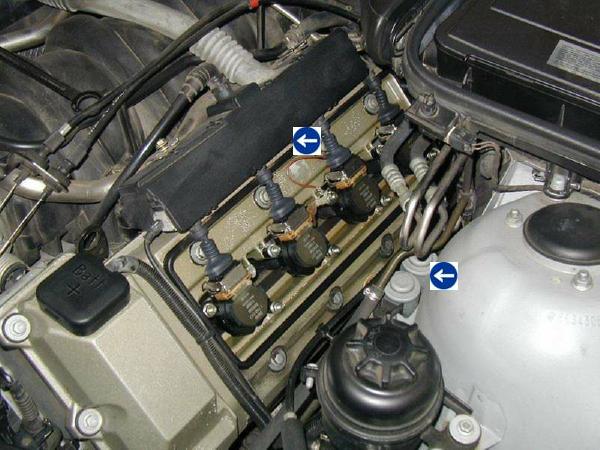
Additional items that also help the level of access needed for the left hand side are removing the 3 cable ties that hold the cable loom that sits against the back of the head and lifting the two solenoids out of their holder on the strut tower (second arrow in above photo)
 having removed the coils and various wires, the cover can be removed by unfastening the retaining elements |
 the layout of the retaining elements is (1) Nut; (2) Washer; and (3) Rubber Mount |

 coat inner and outer grooves and sealing face of covers all around with anti-friction rubber coating then press internal gasket into groove in cover without torsional stress, starting at the four corner radii |
 align outer gasket loosely on groove in cover, secure gasket in groove starting with the corner radii at the back (1) and locate without torsional stress in the groove |
 clean gasket residue from sealing surfaces apply coat of Drei Bond 1209 (BMW parts service) to contact surfaces of joint |  apply Drei Bond to transmission are on half-moon sections |
| The points for Drei Bond are the four corners and two half moons at the rear of the gasket as well as applying some into the half moon sections at the rear of the cylinder head and the contact points arrowed in the above left diagram. You should notice most of these points from the residue on the old gaskets. | |
 check that side of gasket is correctly sealed and check back of cylinder head |
 screw two retaining elements to the locating points, without preload at this stage, and align the cover |
| The half moons are what have to be watched very carefully
during installation, especially on the left side which has the least
access. Popping the fuel line out of the locator on the strut tower gives
a little more room although you need to be careful to not move this too
much to ensure that the fuel rail remains in position.
Once you have checked the gasket right around, install all the other retaining elements and initially just make them finger tight. I don't have any torque settings but if you tighten crosswise working from the from inside to the outside, you only need to apply a gentle force. Then repeat that process, perhaps twice, and you will find them going down a little more. This will vary a little if you have replaced the retaining nut seals. They do not need to be 'nipped' tight at all. If you place your hand just after the T point of your wrench driver - that is minimum leverage on the handle - and tighten to 'wrist' rather than arm strength that will be about right. Double check again after a hot run but any slack then should be minimal.
Future CareWhen leaning into the engine bay, the oil filler cap and the battery terminal cap seem to fall readily to hand as good resting points. They are NOT. Given the angle of the cylinder head (camshaft) covers, this puts unwanted strain on the gaskets you have just replaced - which will increase their propensity to leak again. | |