by Bob Miller, kbob@jogger-egg.com
This note describes how I changed my 1998 BMW M3/4's ASC+T switch (Automatic Stability Control Plus Traction) to automatically turn off ASC+T every time I start the car.
ASC+T is a valuable safety feature, especially on low-traction surfaces. Turn it off at your own risk.
The procedure I describe worked for me in my car. I make no claim that it will work for anyone else or in any other car.
I modified the switch to turn off ASC+T when the car is started. The ASC+T switch is still functional; I can still switch ASC+T on and off at the touch of a button. Because the mod is easily reversible, I can remove it for the winter and reinstall it in the spring.
There are two things about this mod that I don't care for.
First, the ASC+T indicator light in the dash is normally on, indicating that ASC+T is normally disabled. I have learned to live with the light. Actually, I like it; it reminds me how clever I am. (-:
The other misfeature is that if the car is turned off and then immediately turned on, the ASC+T is not disabled. This happens, for example, when the car stalls and is restarted. I hope to figure out a way to fix this eventually. In the meantime, I just push the button.
Testing showed that the ASC+T computer applies 12V between pins 5 and 6 of the switch. Pin 5 is positive, 6 is negative. The switch is a normal single-pole, momentary pushbutton, closed while the button is pressed, and open the rest of the time. The switch's circuit is shown in Figure 1. The computer sees the switch as closed when the resistance between those pins is less than 9K ohms, and open otherwise.
Testing also showed that holding the switch closed while turning on power makes the computer disable ASC+T immediately.
So we need a circuit that has resistance less than 9K ohms for a little while immediately after power is applied, then behaves like a normal switch. Testing showed that "a little while" must be about a second.
The circuit shown in Figure 2 will do that. A little experimentation showed that R = 2.2K ohms, C = 470 uF works well. If you read schematics, it will be obvious why this works. If not, I won't explain it.
You can see why ASC+T is not disabled when the ignition is quickly switched off, then on again. The capacitor doesn't have time to discharge.
As for mechanical construction, I decided to insert the parts into the switch's connector inside the center console. It is merely a friction fit, and the parts are taped in place. This has the advantage that it's completely reversible, and the probable disadvantage that the connection won't stay solid for many years. (It has been reliable for several weeks on my car, though. (-: ) There are certainly many mechanical ways to do it. The way I describe works for me, and something completely different may work for you.
I think the cap is $.99, and the resistors are $.49 for a five pack. We're talking major investment here -- consult your lending institution before undertaking this mod.
1. Solder the resistor to the capacitor. (Do this in your house, not in the car.) Solder either lead of the resistor to the positive lead of the capacitor. Bend the resistor back so that the ends of the two free leads are next to each other.
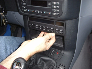
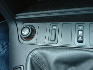
2. Remove the ASC+T switch: Remove the On-Board Computer (OBC) from the dash by inserting your finger into the hole in the top side of the sunglasses storage cubby and pressing the OBC up and out, as shown in Photo 1. Don't unplug the OBC; if you do, you'll have to set its time and date later. Slide the sunglasses tray and the panel housing the ASC+T switch up, as shown in Photo 2. Push the switch up through the panel. Unplug the switch and set it aside. At this point, you can replace the sunglasses tray and OBC, but keep the ASC+T wire accessible.
It's also possible to get to the switch via the shifter boot, but I've found the OBC method easier.

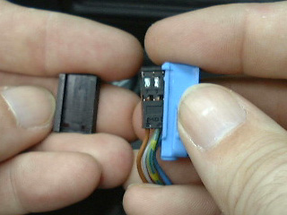
3. Disassemble the ASC+T connector: The connector is female and has sockets for six pins. One side of the connector is black. The black side is a clip. Slide the clip toward the wires and set it aside. Remove the black inner connector from the blue shell and set the shell aside. Photo 3 shows the connector coming apart.
Look at the end of the connector. The sockets are numbered from 1 to 6 with tiny digits molded into the connector. Identify pins 5 and 6. Pin 5 has a green/yellow wire, and pin 6 has a blue/purple wire.
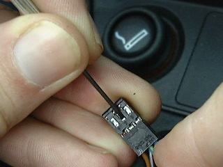
Press the tip of the jeweller's screwdriver through the hole on the side of the connector to release the metal sleeve from pin 5. Photo 4 shows where to press. Pull the wire until the sleeve comes out. Remove the sleeve for pin 6 in the same way.
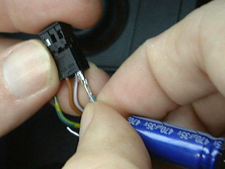
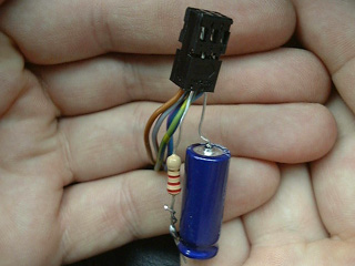
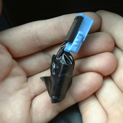
4. Reassemble the connector: Use the pliers or your fingernail to bend the last 1/8th inch of the the resistor's free lead a little, and lay the lead along sleeve 5 so that the bent end bends toward the lead. Slide the sleeve and the lead back into the connector so that the lead is pressing firmly against bare metal. Push it in until it clicks into place. Photo 5 shows the sleeve being inserted. Repeat with sleeve 6 and the capacitor's negative lead. Photo 6 shows the connector with the parts hanging out. Put the blue shell and the black clip back in. Note that the connector only fits into the shell one way.
5. Plug in the switch and test. Turn the ignition on a few times. Verify that the ASC+T light in the dash comes on and stays on. (Actually, it flickers about a second after the ignition is switched on, but then it stays on.) Verify that pressing the switch toggles the light off and on. If it doesn't work, repeat steps 3 and 4 (with the ignition off!) until you have a good connection.
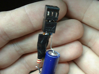
6. Tape it up: wrap electrician's tape around the bare leads so that they can't possibly touch each other, as shown in Photo 7. Bend the resistor and capacitor so that they are snug against the wires leading away from the connector. Tape the R&C securely to the wires, as shown in Photo 8.
7. Test it again. (See step 5.)
8. Push the switch into its hole, as shown in Photo 9.
9. Test it again. Seriously. It took me several tries to get the leads where they reliably made contact with the pins, but once I got it right, it has been quite reliable.
10. Go for a drive. Spin those tires at every stoplight, and command the respect and admiration of discerning motorists everywhere.
Thanks to Brad Smith for lending me his nifty Fuji MX-700 digital camera, and thanks to Anne Eagle for taking the photos on this page.