harness adapter
(archive link: http://www.bimmer.org/5series/messages/archive/msgsy2001w40/27588.html)
Posted by OCJeff on October 05, 2001 at
14:02:01:
In Reply to: Angel eye
install help... posted by Jeff on October 05, 2001 at 13:38:57:
(posted from: spider-ntc-ta071.proxy.aol.com
(198.81.16.51))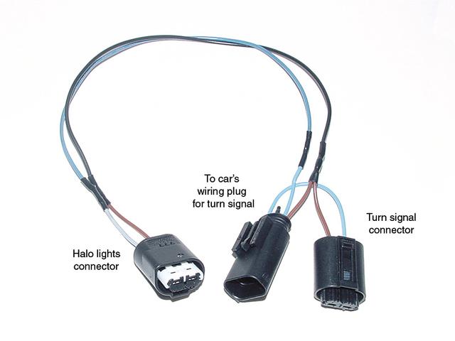
be "Y" shaped. One end plugs directly onto
the plug that used to go to the turn-signal/park-light socket on the old lights.
The other two ends plug onto the new turn-signal socket and the halo bulb. You
can email me directly if you like and I'll talk you through it.
More
from OCJeff.
| Message
Title: Here
goes...... |
Posted by: OCJeff
on 2002-01-26 at 01:57:45
(posted from: Host:
sc-66-27-141-15.socal.rr.com IP: 66.27.141.15) |
Message:
First, here are the wire colors
applicable to my 1998 528. I believe they are the same for all pre-2001 E39's
(except that weird deal where there were only two wires going to the old
turn-signal/parking-light socket. I have no idea what to do there. Most of you
guys will have three wires going to the old socket, and these directions
should do the trick. The A/C tube will need to be **gently** bent out of the
way to accomodate the new halo socket.
For both sides, the brown wire is the common ground that you will use to
ground both the turn-signal and halo lamps.
Left side wire colors:
Blue with green tracer is the hot wire to the new turn-signal socket
Grey with green tracer is the how wire to the halo socket.
Right side wire colors:
Blue with brown tracer is the hot wire to the turn-signal socket
Grey with blue tracer is the hot wire to the halo socket.
First, on the new four-wire connector there is one wire that makes a u-turn
and goes back into the connector. Snip that wire flush with the plastic
connector body at terminal #3. That terminal will not be used in the
fabrication, and you'll need all the remaining wire's length for use later.
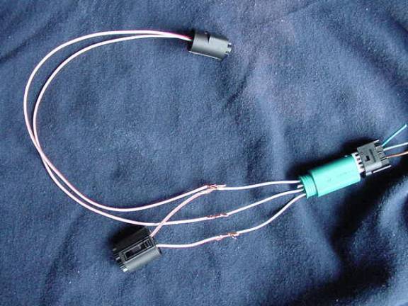
*You should have four mini-harnesses in your hands that were supplied with
your kits. Three of the connectors at the ends of those harnesses will be used
to make the final product (one goes to the original plug that used to hook to
the old turn-signal/parking-lamp socket, and one each for the halo socket and
the new turn-signal socket). The fourth one (the biggest of the four with the
tubular pins) is not used and will be trashed.
**When soldering all these connections, I suggest sliding a piece of
heat-shrink tubing (any electronics store, Radio Shack) over the longest
pieces of wire before soldering, so that you can slide it down over each
soldered joint when you are done, and heat it up with a lighter or match to
make a weather-tight connection.**
*Turn your focus to the only four-pin connector you have. We will deal with
the *left side* harness in this step.
Terminals #1 #2 and #4 of the new four pin connector will be used, and
terminal #3 is unused. This connector is what plugs directly onto the plug
that used to go to your old turn-signal/park-light socket. Make sure it fits
before you proceed.
*Splice the wire leaving terminal #4 of the four pin connector to one of the
wires feeding the connector that fits the halo socket, and one of the wires
feeding the turn-signal socket (the turn-signal wires will be only about 2-3
inches due to the close proximity of the turn-signal lamp socket to the
four-wire connector that hooks to your old plug). Your new lamps will be
grounded when you are finished with this step.
*Connect the only remaining wire on the new plug that hooks to the new
turn-signal (remember, the other is already used up in the prior step) to the
#1 terminal at the back of the four-pin connector (again, you only need a
couple inches of wire between the four-wire connector and the new turn-signal
plug because there is a very short distance for these wires to travel). When
you have completed this step you will have completed the ground and power
circuits to the turn-signal.
*Next, measure how much wire you need to go from four-wire connector to the
halo socket. I figure about ten inches should be enough (that's what she said!
:-} ) Solder the only unused wire in the halo lamp connector (again, the
ground was already establised in the first step) to the wire at pin location
#2 of the four-pin connector. Once you have completed this step you will have
completed the power and grounds for the halo lamps and this entire adapter
harness should be done.
*For the right side harness, you follow the same procedure as the left except
you solder the hot wire of the new turn-signal connector to the wire located
at terminal #1 of the four-wire connector, and the hot wire from the halo
connector to the wire located at terminal #2 of the four-wire connector. The
wire at terminal #4 will again be used to splice into the ground wires of both
the halo and turn-signal connectors. Terminal #3 is again not used, and the
wire leading out of terminal #3 at the four-wire connector should be cut flush
with the back of the connector.
I went over this pretty quick, and may not have been clear about some things.
I invite anyone to email me with questions, or even post them to the board so
all can see the answers. Good luck. It's easier than this diatribe makes it
seem!
| Message
Title: OK, here is
a diagram I've drawn to show how to do |
Posted by: Derek
on 2002-01-26 at 20:01:13
(posted from: Host:
adsl-64-165-200-33.dsl.snfc21.pacbell.net IP: 64.165.200.33) |
Message:
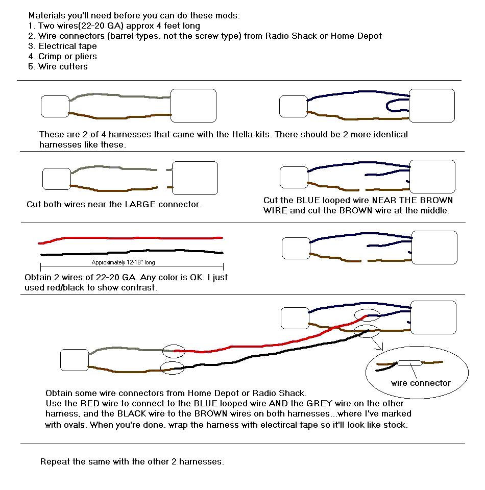
how to modify the harnesses that
come with the Hella Angel Eyes Kits. I've read many are confused with the
actual photos and discription so I made this diagram to simplify it a little
bit. The graphics that symbolized the corresponding parts on the actual
harness may not look real, but you get the picture(pun intended). I'm not
trying to take any credit away from OCJeff(whom I learned this from when I did
mine AE 3 months ago) or anyone else. Just trying to lend a hand.
Hope this helps.
Derek
'90 M3
'99 540i/6 (*OO 00
OO*)