|
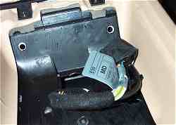
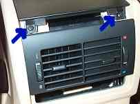
Figure 4. Cables under the
armrest. Also, rear console top retaining screws. |
|
Removal of the armrest reveals the cables that run to the
compartment on the left side of the trunk. There is an antenna cable
with a male mini-UHF connector and a wire bundle with an 18-pin
black plastic female connector.
The two screws at
the top of Figure 4 are the rear retaining screws for the console
top. Remove them. For reassembly, note that these screws
have washers whereas the armrest screws do
not. | |
|
| Console Top
Removal |
| The escutcheon
surrounding the gearshift lever is removed next. Work your fingers
under the escutcheon through the boot as shown in Figure 6. Pull up
to release the clips that attach the escutcheon to the console. See
Figure 7 which also shows the released boot retaining
ring. |
|
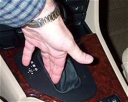
Figure 6. Removing the escutcheon. |
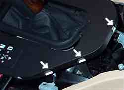
Figure 7. Escutcheon
clips. | |
|
| The retaining ring that
holds the boot to the escutcheon is released by depressing the two clips
on the right side and two clips on the left side of the ring. These
are accessed from the underside of the escutcheon and can be depressed by
feeling their location. Pull the boot up to separate it along with
the retaining ring from the escutcheon. Freeing the boot facilitates
subsequent console top removal. Remove the two console top front
retaining screws shown in Figure 8. Lift the hazard switch up as in
Figure 9 to reveal the console center retaining screw shown in Figure
10. No need to disconnect the wires. Remove the
screw. |
|
|
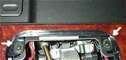
Figure 8. Console top front retaining
screws.
|
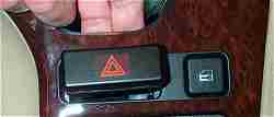
Figure 9. Lifting the hazard
switch.
|
|
|
|
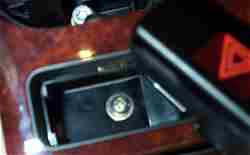
Figure 10. Console top center retaining
screw.
|
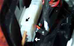
Figure 11. White connector retaining
ears.
| |
|
| Now that all five screws
have been removed, lift the console top up and over the escutcheon to
reveal the white connector to the left of the gear lever that is attached
to a plastic bracket on the console top. The escutcheon has to be
turned sideways in order to get it through the console top. That is
why the boot was loosened. The white connector (Figure 11) is
disconnected by depressing the ears on the top and bottom and pulling the
connector back. The front part of the connector is removed from the
console bracket by pressing down on the small tongue that becomes visible
when the rear connector is removed. Press down on the tongue and
slide the connector forward. Now the top can be lifted over the gear
lever and set aside. There will still be wires attached to various
components on the console top, but the console can be removed, revealing
the space under the console top. |
|
|
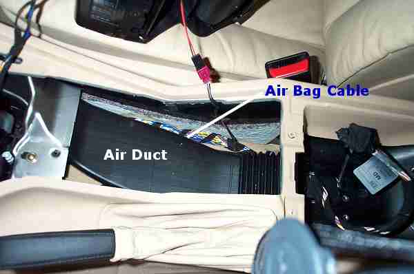
Figure
12. Console top
removed.
|
|
| Do not even think about cutting or splicing the air bag
cable. The two cables from under the armrest are
positioned so that they will lay on top of the airbag cable where they
remain until the extension cables are fabricated. |
|